GPS, Switches & Potentiometer 🎯
Discrete sensors are binary: pressed or not. They feed the safety-stop layer of the control loop. Use them to mask driver input before it reaches the motor.
flowchart TD
    Loop([opcontrol tick — every 20ms]) --> Read[Read all binary sensors:
arm_top.get_value
arm_bot.get_value
front_bumper.get_value]
    Read --> Q1{Front bumper
pressed?}
    Q1 -->|"Yes — collision"| Stop[Cancel all drive motion
chassis.drive_set 0, 0]
    Q1 -->|"No"| Q2{Arm at
top limit?}
    Q2 -->|"Yes"| KillUp[Mask up-button:
want_up = false]
    Q2 -->|"No"| Q3{Arm at
bottom limit?}
    KillUp --> Q3
    Q3 -->|"Yes"| KillDown[Mask down-button:
want_down = false]
    Q3 -->|"No"| Apply[Apply drive/mechanism
commands with masks applied]
    KillDown --> Apply
    Stop --> NextTick([Wait 20ms, repeat])
    Apply --> NextTick

    style Loop fill:#1e293b,stroke:#22d3ee,stroke-width:2px,color:#e2e8f0
    style NextTick fill:#1e293b,stroke:#22c55e,stroke-width:2px,color:#e2e8f0
    style Q1 fill:#fbbf24,color:#0f172a,stroke:#fbbf24
    style Q2 fill:#fbbf24,color:#0f172a,stroke:#fbbf24
    style Q3 fill:#fbbf24,color:#0f172a,stroke:#fbbf24
    style Stop fill:#7f1d1d,color:#fecaca,stroke:#ef4444
    style KillUp fill:#7c2d12,color:#fef3c7,stroke:#fbbf24
    style KillDown fill:#7c2d12,color:#fef3c7,stroke:#fbbf24
Quick Decision Tree
| I need absolute (X, Y) position on the field | Use the GPS Sensor — reads the printed field code on the perimeter walls. |
| I need to know "has my mechanism reached its limit?" | Use a Limit Switch or Bumper Switch — mounts at the end of travel. |
| I need the angular position of a fixed-rotation mechanism (arm, lift) | Use a Potentiometer V2 — reports angle 0–330°. |
| I need to track a continuously rotating shaft (drivetrain, flywheel) | Use the V5 Rotation Sensor (Smart Port). Not covered in this guide — see the sensor onboarding roadmap. |
| I need to detect ring/object color in the intake | Use the V5 Optical Sensor. See the Optical Sensor guide. |
| I need to identify field landmarks for navigation | Use the AI Vision Sensor + AprilTags. See the AI Vision guide. |
How These Three Compare
| Port Type | GPS: Smart Port. Switches and Pot: 3-Wire (ADI) Port. |
| Cost & Complexity | GPS is the most expensive and complex of the three. Switches are the cheapest and simplest. Potentiometer is in between. |
| Output Type | GPS: floating-point X/Y/heading. Switches: digital boolean (pressed/released). Potentiometer: analog 0–330° angle. |
| Setup Difficulty | GPS requires field code strips installed on the field perimeter (already present at official events). Switches and pots work out-of-box. |
| Override Likelihood | All three are useful. Switches are nearly mandatory for any robot with end-of-travel mechanisms. Potentiometer is high-value for arm/lift position. GPS is optional but powerful for skills runs. |
Hardware Summary
| VEX Part Number | 276-7405 |
| Sensor Type | Black-and-white camera + onboard processing. Reads the printed Field Code (a non-repeating checkerboard pattern) on the four field walls. |
| Coordinate System | Origin (0, 0) at center of field. Range approximately −1.8m to +1.8m on both X and Y axes. Reports in meters. |
| Heading Range | 0–360°. Brain screen displays as −180 to +180. |
| Connection | One V5 Smart Port via Smart Cable. |
| Reading Distance | Camera needs to see ~17″ of the field code strip to triangulate position. Robot too close to the wall => reading drops. |
| Mounting Height | ~10.5″ off the ground — in line with the field code strip (per Purdue SIGBots Wiki). |
| Built-in IMU | Yes, but per public forum discussion: the GPS will not transmit angle data unless it has seen the field code at least once every ~10 seconds. Cannot be used as a standalone IMU at home without field strips. |
Mounting Recommendations (per Official VEX Best Practices)
- Mount on the rear of the robot, facing rearward. If mounted on the front, your own scoring mechanism will obstruct the view of the perimeter wall.
- Mount at the height of the field code strip (~10.5″ off the ground). Off-axis vertical mounting reduces detection accuracy.
- Mount parallel to the back of the robot, not at an angle. Keeps the sensor frame parallel to the field walls.
- Right-side up. The VEX logo on the sensor must be upright or coordinates will be reported incorrectly.
- Configure X, Y, and angle offsets in code so the GPS reports your robot's center of rotation, not the sensor itself. (Otherwise your auton math is wrong by the sensor's offset from center.)
PROS API Reference
| Class | pros::Gps |
| Header | #include "pros/gps.hpp" |
| Constructor | pros::Gps gps(uint8_t port); |
| Position | auto status = gps.get_status(); — struct with x, y, pitch, yaw, roll |
| X position only | double x = gps.get_position_x(); — meters |
| Y position only | double y = gps.get_position_y(); — meters |
| Heading | double heading = gps.get_heading(); — 0–360° |
| Set initial position | gps.set_position(x, y, theta); — meters / degrees |
| Set offset | gps.set_offset(x_offset, y_offset); — sensor offset from robot center, meters |
| Position error | double rms_err = gps.get_error(); — RMS error in meters |
| Update rate | gps.set_data_rate(ms); — affects internal IMU only |
GPS Code Pattern (PROS C++)
When the GPS Beats Encoder Odometry
Per the Purdue SIGBots Wiki and the VEX AI overview: the GPS is an absolute position system. It does not drift — the camera always reports where the field code says you are, regardless of how long you've been moving or how much wheel slip occurred.
Encoder/IMU-based odometry (used by EZ-Template and LemLib) is subject to drift — wheel slip, encoder error, and IMU integration error compound over time. After a 60-second skills run, encoder odometry can be off by several inches. GPS readings reset that error every frame.
When NOT to Trust the GPS
- When the camera is occluded. If a game element, an opponent robot, or your own structure is between the sensor and the field walls, GPS readings stop updating. The X/Y will show stale values.
- When too close to a wall. The sensor needs a usable strip width in view. Per VEX Best Practices: too close = the screen shows a circle indicating uncertainty.
- In poor lighting. The camera relies on contrast in the printed code. Dim lighting, heavy shadows, or glare on the wall reduce accuracy.
- During fast spins. Camera-based detection has finite latency; high-speed turns can blur frames.
The pragmatic approach: combine GPS with encoder odometry. Use encoder odometry for moment-to-moment movement; use GPS to periodically reset accumulated drift when readings are reliable.
Hardware Summary
| Bumper Switch v2 (2-pack) | VEX part 276-2159. Spring-loaded button. Two slotted mounting holes; the red button has a removable screw exposing an 8-32 mounting insert. |
| Bumper Switch 6N (2-pack) | VEX part 276-8010. Lower-spring-force version. Activates on lighter touch. Use when the contact force is small (a falling lift arm, a rolling game element). |
| Limit Switch | Spring-steel arm version of the bumper. Arm can be cut shorter or bent. Activated at a 90° angle from the bumper button orientation. Useful when the contact direction is along a different axis than a button. |
| Port Type | 3-Wire ADI port (V5 Brain ports A through H). Three wires: black (ground), red (not connected), white (signal). |
| Logic | SPST normally open. Released = digital HIGH (1). Pressed = digital LOW (0). Per VEX Library: low force needed to activate. |
| Per-Brain Limit | 8 ADI ports (A–H). Each port can host a switch. Use a 3-Wire Expander module if you need more. |
Bumper vs Limit — Which to Use
Mounting
- Bumper Switch: Two slotted mounting holes for #8-32 screws. Use the slots to fine-tune the position so the button just barely activates at the desired contact point.
- Bumper Switch hidden mounting: Remove the red bumper button screw to access an 8-32 mounting insert below. Mount with the button removed if you need a flat profile, then put the button back.
- Limit Switch: Bend or trim the spring arm to fit your geometry. Use the body mounting holes; the arm should sweep into the contact path.
- Cable strain relief: The 3-wire cable is more fragile than Smart Cables. Run cables along structural members, secure with zip-ties at intervals.
PROS API Reference
| Class | pros::adi::DigitalIn |
| Header | #include "pros/adi.hpp" |
| Constructor (port letter) | pros::adi::DigitalIn limit('A'); — ADI port A |
| Constructor (port number) | pros::adi::DigitalIn limit(1); — numeric port 1–8 (A–H) |
| Read state | bool pressed = !limit.get_value(); — note the negation: returns 0 when pressed, 1 when released, so flip to get "pressed" semantics |
| Edge detection | int new_press = limit.get_new_press(); — returns 1 only on the first cycle after a press |
Code Patterns
What Switches Are Best For
- End-of-travel detection for lifts, arms, tilters — protects mechanisms from overrun damage.
- Zeroing reference for arm/lift position — drive against the limit, tare the encoder.
- Mechanism state confirmation — "is the clamp closed?", "is the deploy fully extended?".
- Pre-match auton selector — cycle through routines without using the touchscreen.
- Wall contact for alignment — drive into a wall, the bumper triggers, you know you're flush.
- Failsafe for crashes — if a moving arm could crash into the brain or another mechanism, mount a bumper as an emergency stop trigger.
pros::E_ADI_POT_EDR
pros::E_ADI_POT_V2- Older 3-Wire Potentiometer (red): 250° usable range, 27° deadband at both ends, fragile internal hard stops. PROS constructor:
pros::E_ADI_POT_EDR. VEX install guide ↗ - Newer Potentiometer V2 (black): 333° usable range, no hard stops (more durable). PROS constructor:
pros::E_ADI_POT_V2. VEX install guide ↗
Hardware Summary
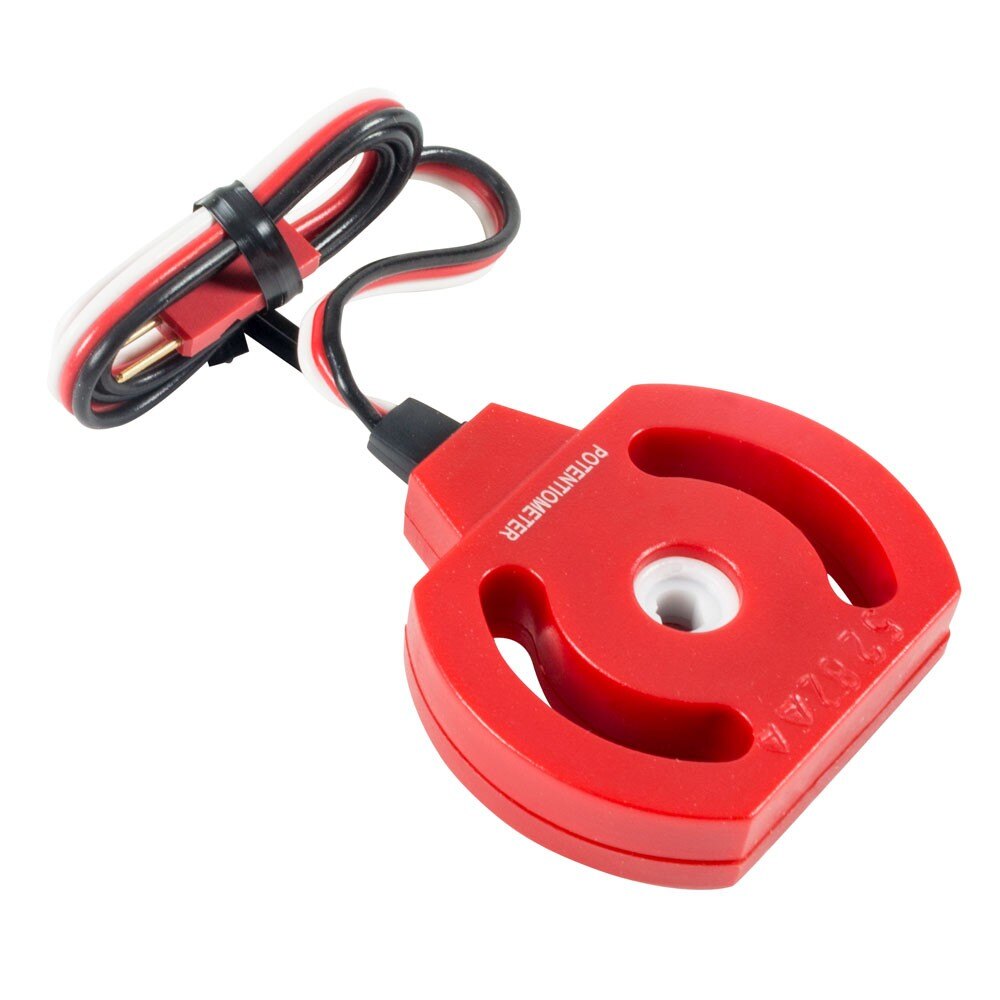
| VEX Part Number | 276-7417 (Potentiometer V2 2-pack) |
| Predecessor | Original Potentiometer (250° range). The V2 is the current model and is what you should use. |
| Rotation Range | Potentiometer V2: 333° sensing range (per PROS docs); the central hub itself rotates 360° continuously, but only 333° of that produces usable readings (there's a 27° deadband). |
| Resolution | 12-bit ADC: 0–4095 raw range. ~12.3 ticks per degree on the V2 across its 333° range. |
| Update Rate | Per public VEX Forum discussion: 10ms refresh through the ADI port (faster than the V5 Rotation Sensor in default config). |
| Port Type | 3-Wire ADI port (A–H). |
| Mounting | Through-hole design with a square shaft passing through the center hole. Two mounting arc slots allow ~90° of fine-tune adjustment after initial mounting. |
| Persistence | Reading is based on absolute physical position. Survives brain power-off — if you rotate the shaft while the brain is off, the new reading reflects the new position when you turn back on. |
When to Use a Potentiometer (vs. a Rotation Sensor)
- Use a Potentiometer V2 when: the mechanism rotates within a fixed angular range (under 333°), and you want absolute position that survives power cycles. Best for arms, lifts, tilters.
- Use a V5 Rotation Sensor when: the shaft rotates continuously without limit (drivetrain wheels, flywheels, tracking wheels for odometry). Smart Port-based, higher precision.
- Use a V5 Smart Motor's built-in encoder when: the shaft is directly driven by a Smart Motor and you don't need encoder data when the mechanism could be back-driven by an opponent or external force.
Per the VEX Library: do not force the Potentiometer past its mechanical stops. The V2 design is more durable than the original (conductive plastic resistive track instead of mechanical resistive material), but forcing past 333° can still damage the internal stops, leaving the sensor permanently unreliable.
Mounting
- Through-hole design: Pass a square shaft (typically the same shaft your mechanism rotates on) through the center hole.
- Mounting arc slots: Two slotted screw holes on the body let you rotate the sensor body relative to the shaft. Use this to position the "dead band" at an angle the mechanism never reaches.
- Mount directly under a V5 Motor: The body is sized to mount directly underneath a V5 Smart Motor — the mechanism shaft passes through both the motor and the potentiometer.
- Calibration on install: After mounting, manually move the mechanism through its full range. Verify the potentiometer never enters its 27° deadband. Adjust the body within the arc slots if needed.
PROS API Reference
| Class | pros::adi::Potentiometer |
| Constructor | pros::adi::Potentiometer pot('A', pros::E_ADI_POT_V2); — specify V2 type for 333° mode |
| Original pot type | pros::E_ADI_POT_EDR for the legacy 250° potentiometer |
| Get angle | double angle = pot.get_angle(); — degrees (0 to 333 for V2) |
| Get raw value | int raw = pot.get_value(); — raw 12-bit ADC value (0–4095) |
| Calibrate (optional) | pot.calibrate(); — collects 500 samples over 0.5s, accounts for sensor noise |
Code Pattern: Arm Position Control
Calibration Procedure
Before competition, run a calibration to understand your mechanism's actual range and pot readings:
- Mount the potentiometer with the deadband out of normal mechanism travel.
- Move the mechanism to its physical lower limit (e.g., arm fully down). Record the pot angle. This is your
ARM_DOWN_DEG. - Move the mechanism to its physical upper limit. Record the angle. This is
ARM_UP_DEG. - Move to known intermediate positions. Record. Build a lookup of named positions (LOAD, SCORE_LOW, SCORE_MID, SCORE_HIGH).
- Use these values in your code as named constants. Don't assume the mechanism mounts identically across robots — mounting tolerances mean you re-calibrate per robot, sometimes per pot.
Tracking Wheel Use (Advanced)
Per a public VEX Forum discussion (July 2021): some teams use two Potentiometer V2s as tracking wheel encoders for odometry, alternating between them to avoid the deadband. The 333° range gives ~12× the resolution of older quadrature encoders, with 10ms refresh. This is an unusual approach — most teams use the V5 Rotation Sensor for tracking wheels because LemLib and EZ-Template have direct support for it. We mention it for completeness; it's not the recommended path for new teams.
The Honest Picture
Same as for the AI Vision and Optical sensors:
- EZ-Template and LemLib wrap the drivetrain: motors, IMU (one specific sensor), and optionally tracking wheel encoders/rotation sensors. They handle PID, odometry, motion profiling.
- They do NOT wrap GPS, switches, or potentiometers. For those you use the standard PROS API directly.
- Integration happens in your auton code: compose chassis motion calls with sensor reads.
GPS + EZ-Template: Position Reset Pattern
EZ-Template uses encoder-based odometry by default. That odometry drifts. The GPS doesn't. Combine them: let EZ-Template handle motion, then periodically reset its odometry from GPS readings.
Note: The exact EZ-Template odometry-set function name may vary by version. Check the EZ-Template tutorials for the current API. The pattern is correct; the function name might be odom_pose_set, odom_xy_set, or similar in your installed version.
Limit Switch + EZ-Template: Drive-Until-Wall Pattern
Drive forward with EZ-Template PID, but exit early when a bumper switch triggers (e.g., when the robot bumps into a field wall or fixed structure).
Potentiometer + EZ-Template: Async Subsystem Pattern
EZ-Template focuses on the chassis. Subsystems (arm, lift) run in parallel tasks. Use a potentiometer in your subsystem task to track and control its mechanism while EZ-Template handles driving.
LemLib Equivalents
EZ-Template chassis.pid_drive_set | LemLib chassis.moveToPoint or chassis.moveTo |
EZ-Template pid_targets_reset | LemLib chassis.cancelMotion |
EZ-Template pid_wait | LemLib chassis.waitUntilDone |
EZ-Template odom_pose_set | LemLib chassis.setPose(x, y, theta) |
Both libraries support the same composition patterns. LemLib's odometry sensor structure (lemlib::OdomSensors) takes pointers to your tracking wheels and IMU; you pass GPS-derived corrections to setPose() when you want absolute position resets.
GPS for Override
- Skills run drift correction. Highest-value GPS application. 60-second autonomous runs accumulate encoder error; periodic GPS resets keep your position accurate to the end. Note: Override scoring happens at goals (wall-adjacent positions), which is the GPS deadzone — pair with another absolute-position sensor for goal-approach precision. See sensors-gps § GPS vs. AprilTags.
- Quadrant awareness. Override divides the field into 4 quadrants. The GPS can tell your code which quadrant your robot is currently in — useful for selecting the right toggle to flip or the right alliance goal to score on.
- Cross-field navigation. Override scoring is distributed (4 alliance goals + 4 short neutrals + 1 tall center). The GPS handles long-distance navigation between scoring zones better than encoder odometry alone.
- Anti-pin strategy. If you get pinned by an opponent, your encoder odom thinks you moved (motors spinning) but the GPS shows you stayed put. Detect the discrepancy, exit the pin.
Limit/Bumper Switches for Override
- Arm/lift end-of-travel. Override arms move between presets (ground, low goal 3.25″, mid 5.8″, high 8.7″). Limit switches at top AND bottom prevent motor stall and mechanism damage. Cheap insurance.
- Endgame collapse confirmation. Override's endgame requires collapsing to ≤18″ in 10 seconds (SG12.1). A bumper switch at the arm's collapsed position confirms the arm reached the endgame-legal height before the buzzer. See override-endgame.
- Wall alignment. Front-mounted bumpers let you drive against a wall, register the contact, and use it as a position reset. Useful for resetting between scoring sequences.
- Pre-match config. One bumper as auton selector, one as alliance-color toggle. Saves screen-tap time at the start of matches. (Identical to past seasons.)
Potentiometer for Override
- Arm position control. The Override Hero Bot baseline has an arm with multiple discrete presets (ground, low, mid, high). A potentiometer gives absolute angle feedback — cleaner than relative encoder counts when the arm needs to return to known positions repeatedly. See advanced-robot Chapter 2 for the preset pattern.
- Cup-flip mechanism feedback. If your manipulator flips cups before placement (to correct opaque/transparent orientation), a potentiometer can confirm the flip completed. See sensors-optical § Override Use Cases for the cup-orientation problem this solves.
- Tilter feedback. If your scoring mechanism tilts (e.g., a swinging arm to deliver objects), the pot tells you the angle precisely.
Pre-Order Hardware List for Override
- Bumper Switches: Order at least 4–6 per robot. Cheap (276-2159 2-pack), versatile, you will use them.
- Limit Switches: 1–2 per robot. Use where the contact direction or sweep geometry favors the steel arm over the bumper button.
- Potentiometer V2: 1–2 per robot. One per major mechanism with limited rotation (arm, lift, tilter, cup-flip).
- GPS Sensor: 1 per robot. Most useful for skills runs. Optional for match autons (encoder odom is usually sufficient for 15s).
- Smart Cables & 3-Wire Extension Cables: Plenty of spares. The 3-wire cables are more failure-prone than Smart Cables.
GPS Pitfalls
- Mounted upside-down. VEX logo MUST be upright. Wrong orientation = wrong coordinates. Verify in the V5 brain Devices screen.
- Mounted at wrong height. ~10.5″ off the ground is the target. Too high or low and the camera misses the field code strip.
- Forward-facing. Game elements and your own scoring mechanism block the view. Mount rear-facing.
- Practice without field walls. Without the printed field code strips, the GPS does NOT work. Plan accordingly — either invest in the strips for your practice setup, or do GPS testing only at competitions.
- Trusting GPS during a pin. If an opponent shoves your robot, the GPS tracks accurately, but encoder odometry will diverge. Use the divergence as a pin-detection signal.
Switch Pitfalls
- Forgetting the negation.
get_value()returns 1 when released, 0 when pressed. Beginners frequently invert the logic and the switch "does nothing." - Cable loose in 3-wire port. 3-Wire ports are friction-fit. Cables can wiggle out during rough matches. Use cable management.
- Limit switch arm bent. The steel arm can deform from hard impacts. Check all your switches at every pit stop. A bent arm gives wrong trigger geometry.
- Mounting too rigid. If a bumper is mounted such that the mechanism slams into it at full speed, the switch breaks. Slow down before contact, or add a small foam buffer.
- Wrong port assumption. ADI port 'A' is port 1, 'B' is port 2, etc. Make sure your code references match the wiring.
Potentiometer Pitfalls
- Rotating into the deadband. The 27° deadband (V2) returns garbage values. Use the body's arc slots to position the deadband out of mechanism travel.
- Forcing past the mechanical stops. Damages internal stops, sensor becomes free-rotating and useless. Discard if this happens.
- Wrong type in PROS constructor. If you pass
E_ADI_POT_EDRfor a V2 sensor, the angle range is reported as 250° instead of 333°. Always use the matching enum. - No calibration. Mounting tolerances vary. Two robots with identical mechanisms can read different pot angles for the same physical position. Calibrate each robot, each pot.
- Hard-coded thresholds. If the pot drifts (mounting screws loosen, sensor body shifts), your hard-coded angle constants become wrong. Re-calibrate at every venue if you can.
Skills Run Tips
- Use switches as zeroing references. Drive against limit switches at the start of skills; tare encoders. This guarantees your starting position is the same every run.
- Use the GPS for mid-run resets. Add a couple of position-resync points partway through your skills sequence. Lets you recover from accumulated drift.
- Use the potentiometer for arm/lift presets. Hardcoded motor-time-based arm moves drift. Pot-feedback moves are repeatable.
- Test under match-day venue conditions. GPS depends on lighting; switches depend on mounting integrity; pot depends on physical alignment. Re-test at every new venue.
Driver Skills Tips
- Limit switch macros. A controller button that runs "arm down until limit, then tare" gets the arm to a known position fast. Driver doesn't have to manually align.
- Pot-driven preset buttons. Map controller buttons to specific arm angles via the potentiometer. Driver presses button = arm goes to that angle. No manual tuning.
- GPS for "return home" macro. A button that auto-drives the robot back to a known field position (e.g., your loading zone). Saves driver time during fast skills runs.