Why the Clawbot is the Right Sensor Testbed
- Fixed geometry. Every Clawbot is the same. Mounting positions you find on yours work on every other team's Clawbot. Calibration values transfer directly across robots.
- Limited mechanism count. Drive + arm + claw. Three subsystems, three places to mount sensors. Nothing more to debug than the sensor itself.
- Already built and working. If something breaks during sensor testing, the breakage is the sensor or your code, not the Clawbot.
- Pressure-free. No tournament countdown, no game elements, no opponent. Pure learning environment.
Seven Clawbot Sensor Exercises
Work through these in order. Each one introduces one sensor and teaches one calibration pattern. Total time: ~5–6 practice sessions.
Every V5 Smart Motor has a built-in optical encoder. EZ-Template's drive PID, your tare_position() calls in arm code, and every PROS function that returns a motor's degrees or RPM all read from this same sensor. You've been using it since Section 2 — you just haven't seen it directly. This exercise pulls back the curtain.
Three concrete tasks:
- Read raw position. Print the four drive motors' encoder positions to the V5 Brain screen while driving manually. Watch the numbers change. Notice that left and right motors don't always match — that's drift, scrub, and slip showing up in real time.
- Convert degrees to inches. Given wheel diameter and gear ratio, calculate how far the robot has actually traveled. Drive 24″ by tape measure. Compare what the encoder says. If it's off, your constants are wrong.
- Detect a stall. Read encoder velocity. When velocity stays at zero while voltage is applied, the motor is stalled (jammed, overloaded, or burned out). Print a warning. This is the foundation for the failsafe pattern you'll use in Section 6.
Goal: Build the mental model EZ-Template needs to do its job. When PID misbehaves, encoder data is the first thing you check — almost every drive PID failure is one of: wrong wheel diameter, wrong gear ratio, or wheel slip. All three are visible in this dashboard. See sensors-rotation for the external Rotation Sensor (V1.1 upgrade for higher precision) and motor-troubleshooting for stall diagnostic patterns.
Important framing: EZ-Template handles the drive PID for you using these encoders. You're learning to read encoders so you can debug and integrate, not so you have to write your own PID. Don't replace EZ-Template's drive PID with your own — that's a different, much harder exercise.
Mount one limit switch at the bottom of the arm's travel and one at the top. The Limit Switch (VEX 276-2174) is the right part for mechanism endpoints — its bendable spring-steel lever is designed for light, repeated contact. Don't use a Bumper Switch here — that's the harder plunger-actuated part, designed for collision detection (you'll use one as a front bumper in Exercise 6). In code, use the limit switches to: (a) prevent the arm motor from running past the limits during driver control, (b) zero the arm encoder by driving the arm down until the bottom switch triggers, then calling tare_position().
Where to mount each limit switch
Bottom limit (ADI port B). Mount it near the front of the chassis, low, where the arm c-channel rests when the arm is at its lowest position. Two reasonable spots on the standard V5 Clawbot:
- Option 1 (preferred): on the front cross-channel of the chassis, lever pointing up. The arm c-channel rests on top of the lever when the arm is fully down. This auto-presses the switch at startup, which means the very first thing your code can do in
initialize()is readarm_bot_limit.get_value(), confirm it's0(pressed), and callarm.tare_position()to zero the encoder. No homing routine needed. - Option 2: on the inside face of the arm pivot tower, near the bottom, with the lever sticking out horizontally into the arm's swing path. The arm presses the lever as it rotates down to its lowest position.
Top limit (ADI port A). Mount it on the inside face of the arm pivot tower, roughly 2–3 inches below the upper hard stop. The lever should be horizontal, pointing inward into the arm's swing path. As the arm rotates up to its highest commanded position, the arm c-channel presses the lever just before hitting the hard stop — that's the soft-limit you want, so the motor cuts off cleanly without slamming the hard stop.
Verify before wiring. Manually rotate the arm through its full range and confirm: (1) the bottom switch lever depresses smoothly when the arm is at the bottom, (2) the top switch lever depresses smoothly when the arm is at the top, (3) the arm c-channel doesn't bind on either lever during normal travel, and (4) neither switch is pressed when the arm is in its mid-range working zone. If you hear a click as the lever bottoms out and the arm keeps moving past, your switch is correctly positioned. If the arm gets stuck or the lever bends past its travel limit, reposition the switch.
Wiring. Three-wire cable from each switch to the V5 Brain's ADI ports. Color convention is red/black/white — either orientation works for digital switches because they're symmetric, but the standard is white-stripe-up. Top switch goes to ADI port A, bottom to ADI port B. The code below assumes this mapping.
Goal: Understand digital sensors. Learn the !get_value() negation gotcha (returns 0 when pressed). See the switches guide for full PROS API and the VEX KB article on Limit Switch installation ↗ for the official mounting guide.
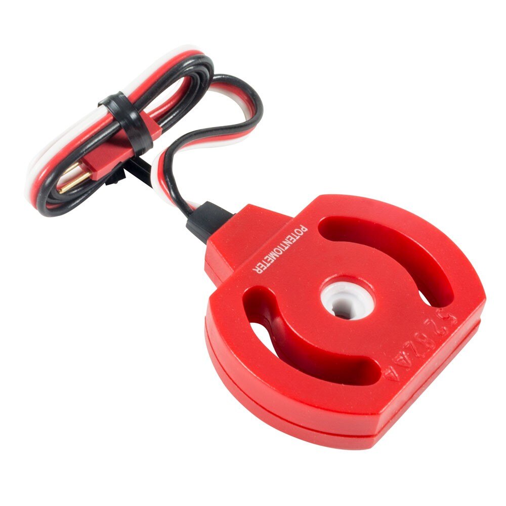
Spartan Design's team uses the older red 3-Wire Potentiometer — 250° electrical range, fragile internal stops at each end. Do not rotate it past 265°: VEX’s install guide ↗ warns “the sensor’s internal stops can be broken allowing the hub to free rotate” if forced. Once that happens, the pot is recyclable trash.
Step-by-step workflow:
- Install per the VEX KB install guide — D-hole over the arm pivot shaft, two screws through the mounting arc slots, attached to a structural piece.
- Power on the V5 Brain with the pot wired to a 3-Wire ADI port (the team uses port C). Tap Devices on the brain’s touchscreen, then tap the potentiometer’s port. The screen will show the live raw value (0–4095) or angle.
- Manually rotate the arm by hand through its full intended range (down position → up position). Confirm the value changes smoothly and continuously — no sudden jumps to 0, no plateaus, no weird gaps. Note the values at
ARM_DOWN,ARM_MID,ARM_HIGH. - Show the mentor your range. Confirm with them that the values stay within the pot’s 0–250° safe arc and don’t approach the hard stops.
- Only after mentor approval: wire to the Brain ADI port and power up the motors. Now you can run the code below.
Goal: Understand absolute position sensing. Learn that pot readings persist across power-cycles (encoder readings don't). Replace your previous encoder-based arm presets with potentiometer-based ones. See the potentiometer guide.
Build a PROS task that prints the live values of every sensor on your Clawbot to the V5 Brain screen continuously. Lines should include: IMU heading, IMU rotation, arm pot angle, both limit switch states, battery percentage. Use this as your debugging surface for everything that follows.
Goal: Learn the pros::lcd API. Develop the habit of always having sensor data visible on the screen. See V5 screen calibration for the pattern.
Mount an Optical Sensor inside or just behind the Clawbot's claw, pointing at where a held object would sit. Use color to detect whether something is held, and what color it is. Build a driver-assist macro: when the claw closes on an object, print the detected color to the brain screen.
How to mount it: VEX’s Mounting and Wiring the V5 Vision Sensor ↗ article documents the gusset-and-bracket technique for the Clawbot claw — and explicitly states “other sensors can use the same mounting method.” Use a 90° Flat Gusset on top of the claw + an Angle Gusset to the back of the sensor, with two #8-32 × 3/8″ screws for each. The Optical Sensor is smaller than the Vision Sensor, so the same mounting has more clearance. See also the STEM Lab walkthrough ↗ with photos.
Goal: Practice short-range sensor mounting (the < 100mm rule). Calibrate hue ranges per object color. Learn proximity-gating (don't trust hue when proximity is low). See the Optical Sensor guide.
Mount a V5 Distance Sensor on the back of the Clawbot — not the front. The claw sits in front and would either block the sensor or get measured itself. Back-mounted, the sensor measures distance to the field perimeter wall, which is the standard V5RC technique for autonomous start-position correction.
Build a routine that drives the Clawbot backwards until the sensor reads a target distance (e.g. 100 mm from the wall), then stops. Confirm the position is repeatable: run the routine 5 times and verify the final distance is within ±10 mm each time.
Goal: Eliminate auton drift from start-position error, battery voltage, and floor friction. Same technique top V5RC teams use. See distance-sensor-auton for the full PROS implementation pattern (wall correction during autonomous, drift elimination).
Field practice intelligence for qualifier squad: the perimeter wall’s reflectivity affects laser distance readings. Calibrate your values on the actual Override field, not just the lab. Note any deltas in your notebook — qualifier squad needs your numbers when they wire up V1.
Re-do Exercise 5 from the previous section (Full Mission Autonomous), but replace every timed action with a sensor-triggered one: drive forward until limit switch hits the wall, raise arm until pot reaches ARM_HIGH, close claw until proximity drops (object grabbed), turn until IMU heading is target, drive backwards until distance sensor reads target distance from rear wall. Time-based motions should disappear entirely.
Goal: See the difference between time-based auton (brittle, drifts) and sensor-based auton (robust, repeatable). The same skill transfers directly to your competition robot. The Clawbot is teaching you the discipline that wins matches.
Sensor Worked Solutions 📖
Sensor Exercise 0 — Motor Encoder Dashboard
opcontrol() body with this for the exerciseWhat you're seeing. Each motor encoder counts in motor degrees — 360° per motor revolution, NOT per wheel revolution. That's why GEAR_RATIO matters in the conversion. The Clawbot is direct-drive (1:1) so motor degrees = wheel degrees. On a geared drivetrain (say a 5:3 reduction), you'd set GEAR_RATIO accordingly — e.g. 1.667 for 5:3 (or its inverse, depending on direction of math) to get accurate inches.
Why this matters for PID debugging. When EZ-Template's drive PID overshoots a target distance, the issue is almost always one of three things: (a) WHEEL_DIAMETER constant is wrong, (b) GEAR_RATIO is wrong, (c) wheels are slipping (encoder counts don't match actual ground travel). All three are visible in this dashboard. Try this: run the dashboard, drive the robot 24 inches by tape measure, check what the encoder reports. If it says 23 inches, your conversion is off by ~4%. If it says 24 inches but the robot only moved 18, you're slipping — the wheels spun but didn't translate.
The stall detector uses the same logic motor protection libraries use internally: voltage applied (>1V) plus velocity near zero (<5 RPM) means something is jammed. Print a warning, optionally cut motor voltage to prevent overheat. This is the foundation for the failsafe pattern you'll see in Section 6 — once you can detect a stall, you can recover from it instead of letting your robot overheat or your auton drift forever waiting for a target it'll never reach.
WHEEL_DIAMETER_IN constant is set smaller than the actual wheel sizeWHEEL_DIAMETER * π / 360 / GEAR_RATIO. If the constant is set smaller than reality (say 3.5″ when wheels are actually 4″), each motor degree maps to fewer claimed inches than the actual ground travel. EZ-Template stops when it thinks 24 inches were reached, but the actual travel is larger. That's an overshoot. Slip causes the OPPOSITE problem: motor turns more than ground travel, encoder reports more inches than actual, EZ-Template stops early — UNDERshoot, not overshoot. The IMU governs heading, not distance. PID tuning could cause overshoot but the encoder reading would also overshoot (it'd say 26", not exactly 24"). The fact that the dashboard reads exactly 24" while the robot traveled 30" is the signature of a wheel-diameter constant error.Sensor Exercise 1 — Limit Switches on the Arm
Why !get_value(): the Limit Switch — like the Bumper Switch and most pull-up-style ADI digital inputs — returns 0 (false) when pressed and 1 (true) when released. Negate to get readable variable names like at_top. Forgetting this is the most common limit-switch bug. The auto-zero pattern at the bottom is the magic — every time the arm bottoms out, the encoder resets to zero, which keeps your ARM_MID/ARM_HIGH presets accurate even if the arm motor is power-cycled mid-match.
Sensor Exercise 2 — Potentiometer on the Arm
src/robot-config.cpp) goes at file scope — outside any function, after #include, alongside the other pros::Motor and pros::Imu declarations EZ Template already has. The control function (file src/main.cpp) goes alongside your other helper functions and is called from opcontrol(). Copy and paste at the indicated locations.Why pot beats encoder for arms: the pot reads absolute angle. Power-cycle the robot, the angle is still right. Encoder zero drifts unless you pair it with a limit switch (Exercise 1) or a homing routine. For competition robots with arms, pot is the standard. Tune arm_pot_pid kP/kD until the arm holds position smoothly without oscillation. The older red pot has a 250° usable range with hard stops at each end — the team’s mentor-check workflow above exists to verify your arm’s full travel stays inside that range. If your team has the newer black V2 pot, change one line: pros::E_ADI_POT_EDR → pros::E_ADI_POT_V2. The V2 has 333° of travel with a 27° deadband at the ends and no hard stops — mount the pot so the arm’s full range stays inside that.
arm_pot_pid live with the X-button tuner. Same pattern as drive PID and the encoder-based armPID from Section 04. Add this one line to initialize() after the arm_pot_pid declaration:
X on the controller, navigate with D-pad until you see "ArmPot PID", and adjust kP/kD with the joystick while pressing B to test. See Section 5 Exercise 3 for the full tuner walkthrough — the workflow is identical for every PID you register.Sensor Exercise 3 — Brain Screen Calibration Dashboard
Why a separate task: the LCD update runs in the background at 10 Hz without blocking your control loop. pros::Task creates a free-running thread that calls dashboard_fn() forever. The control loop in opcontrol() stays at 50 Hz; the dashboard updates 5× slower. The fast loop doesn't need to know about the dashboard. This task-based separation is exactly how you'll structure competition code.
Sensor Exercise 4 — Optical Sensor on the Claw
Why proximity-gate before hue: when nothing is held, the sensor sees ambient light and returns garbage hue values that fall randomly into one of your color ranges. Filtering on get_proximity() < 100 (under 100mm) means "something is close enough to read reliably." Without this gate, your auton would think it grabbed a red object every time the claw closed on air. Hue ranges shown are nominal — calibrate at your venue with the actual objects under the actual lighting.
Sensor Exercise 5 — Distance Sensor on the Back (Wall Reset)
src/robot-config.cpp alongside other Smart Port devices (motors, IMU). The extern goes in include/main.h. The wall-reset function goes in src/main.cpp alongside other helper functions and is called from autonomous() as the first line of every auton routine.Why this beats encoder-based starting position: motor encoders count from where they were last zeroed. If your robot is placed even 10mm off in the start box, every encoder-based motion compounds that error through the auton. The wall is a fixed reference. Drive to it once at the start and you’ve eliminated start-position error from the entire match. Calibrate target_mm on the actual Override field — the perimeter wall’s laser reflectivity differs from lab walls. The team observed a ~5mm delta between lab and field; expect the same. See distance-sensor-auton for the full technique including mid-auton wall corrections.
Sensor Exercise 6 — Sensor-Driven Auton Mission
Replace every timed action from Exercise 5 (in the previous section) with a sensor-triggered one. This exercise uses one new piece of hardware — a bumper switch on the front of the chassis that detects when the robot has reached the goal wall.
pros::adi::DigitalIn, returning 0 when pressed). The difference is physical: the Bumper Switch has a spring-loaded plunger built for repeated wall contact; the Limit Switch has a thin spring-steel lever built for light mechanism endpoint contact. Bumper Switch v2 product page ↗ · VEX KB: Bumper vs Limit ↗. Use a bumper switch here for durability — the lever on a limit switch will bend and eventually break under repeated wall slams.
Where to mount the front bumper: on the front face of the chassis, low — around 2–3" off the ground, below the arm pivot tower. Mount it via the two slotted holes on either side of the bumper housing (use 8-32 screws with the screws not too tight or the plastic cracks). Orient the bumper so the red plunger points forward — it gets compressed when the chassis hits the wall.
POT_ARM_HIGH when the wall-bumping drive runs. When the arm is down or at mid, the claw extends forward of the chassis at low height. If you drive into the wall in those poses, the claw hits first and the bumper never triggers — the robot will hang in the while loop until the timeout expires (or forever, in the buggy old version). The mission below raises the arm to HIGH in Phase 4 specifically so Phase 6's wall drive works. Don't reorder these phases.
If you build a competition robot whose game-piece manipulator stays low even when scoring (e.g., an intake roller instead of a claw on an arm), you'll mount the front bumper differently — high enough that the manipulator clears it. The principle is the same: the bumper has to be the first part to touch the wall when you drive forward, regardless of mechanism state.
What changed from Exercise 5 in the previous section: every timing-based wait is now a sensor-based condition with a timeout safety. The optical sensor tells you when an object is close enough to grab. The pot tells you when the arm is at the right height. The bumper tells you when you've reached the wall. The IMU (already used internally by EZ-Template's pid_turn_set) tells you when you've completed the turn. Every while loop has a millisecond cap so a sensor failure never hangs the auton. To stop a PID-driven motion partway through, the canonical EZ-Template pattern is chassis.pid_targets_reset() followed by chassis.drive_set(0, 0) — the first cancels the active PID target, the second commands the motors to zero. The mission completes correctly across battery voltages, friction variations, and minor robot wear that would break a time-based version. This is the discipline that wins matches.
Final main.h Reference
By this point the curriculum has incrementally added a lot of hardware and helpers. If you start hitting linker errors when calling sensor functions or shared constants from autons.cpp, that's because every cross-file symbol needs an extern (for variables) or a prototype (for functions) in main.h. Here's the complete header your project should have by the end of Section 6:
Why this matters. The progressive blocks in this section each show only the incremental change — "add this line to robot-config.cpp," "add this extern to main.h." That works perfectly while you're working in one file, but as soon as autons.cpp calls something defined in main.cpp (like the constants or read_held_color()) the linker needs to know where to find them. extern for variables, prototypes for functions — everything in main.h, included by every .cpp file. Add to this header as you add new hardware in your own work.
get_value(). Is the limit currently pressed?get_value() for readable codebool at_top = !arm_top_limit.get_value(); — the negation makes the variable name and the value match human intuition, and the rest of the code reads cleanly.wall_reset_back() called as the FIRST line of every auton routine?- Limit switch always reads 0 (pressed). Either the ADI port in code doesn't match the physical wiring, or the switch is depressed by something at rest (cable pressing on it, mounting bracket too tight). Verify on the brain's device-screen.
- Optical sensor reads 0 proximity always. Did you call
claw_optical.set_led_pwm(100)ininitialize()? Without the LED on, the sensor sees ambient light only. - Distance sensor reads jumpy values. Reflective surface (chassis aluminum, claw structure) too close to the sensor's beam path. Reposition or angle slightly so the beam clears the robot's own structure.
- "undefined reference to
read_held_color" build error.main.his missing the prototype. The "Final main.h Reference" block at the end of this section shows the complete header with every extern and prototype. - Sensor-driven mission gets stuck in a while-loop. Did the sensor condition ever actually trigger? Add a
pros::lcd::print()inside the loop to verify. Also: everywhile (sensor)needs a max-iterations or elapsed-ms cap so a sensor failure doesn't freeze the auton.