vexrobotics.com/v5/competition/vrc-current-game, import that and retire these placeholders.- Prerequisites. If you haven't logged into Onshape yet or you're fuzzy on basic sketching, work through Onshape Setup (DUSD account login, ~10 min) and the Onshape Intro Video Series (sketch + revolve + extrude basics, ~20 min) before starting Section 2. This guide assumes both.
- Set your units to millimeters before you sketch. Override is a metric game (the toggle is 660.2 mm). If your part studio defaults to inches, your dimension labels will look like
26.0when the manual says660.2— not because anything's wrong, but because that's 660.2 mm in inches. Fix it once at the start: open the document → Workspace units → choose Millimeter. - Save a version when each element is done. Onshape autosaves continuously, but autosaves don't give you a named checkpoint. Use the Versions and history panel to save
Cup v1 done,Pin v1 done, etc. If a later edit breaks something, you can branch off the named version instead of undoing 200 steps. - If you're stuck for 15 minutes, ask. Pair with a teammate who's already finished the element you're working on, or post the issue (with a screenshot of the sketch) in the team's build channel. The most common first-timer mistake — sketching on the wrong plane — takes 30 seconds for someone else to spot and 30 minutes to find on your own.
Why Build These at All
Three real reasons:
- Hero Bot fitment. "Does the manipulator clear the cup at the top of the goal?" can't be answered without elements in the assembly. CAD-checking before fab saves rework.
- Design-review visualization. Showing "this is how the robot interacts with the field" in CAD makes design reviews faster and gets better feedback.
- Notebook deliverables. The 2026-27 notebook template (Slide 13 Field Elements) wants concrete element references. Building them yourself produces good notebook content.
What You'll Build
| Element | Build operation | Walkthrough |
|---|---|---|
| Cup | Sketch half-profile → revolve 360° | Section 3 (Cup tab) |
| Pin | Sketch hex profile + side profile → stacked extrude or loft | Section 4 (Pin tab) |
| Goals (3 sizes) | Sketch top profile → extrude × 3 heights | Section 5 (Goals tab) |
| Toggle | Sketch triangle → extrude 660.2mm | Section 6 (Toggle tab) |
Where This Fits in the Curriculum
This page supports the Phase A Onshape sessions (Mtgs 4–8, May 7–21). Specifically:
- Mtg 4 (Onshape Day 1): Cup is a clean introductory exercise for sketch-and-revolve.
- Mtg 6 (Onshape Day 2): Drivetrain CAD references the field elements for scale.
- Mtg 8 (Onshape Day 3 — Mechanisms): Manipulator CAD assemblies need the cup and pin imported as parts.
For the print-friendly version of this walkthrough (single document, no per-section navigation), see Section 8 (Notebook tab).
The Team Pattern
Whether the element is a cup (revolve), a pin (stacked extrude), a goal (extrude with hole), or a toggle (extrude prism), the workflow is the same five-step pattern:
Sketch the 2D profile on the right plane
Front plane for revolves (cup, anything radially symmetric). Top plane for extrudes (pin, goal, toggle — anything with a flat base footprint). Use a vertical centerline for revolves; the centerline becomes the axis of revolution.
Apply dimensions until the sketch is fully defined
Onshape shows under-defined geometry in blue. As you add dimensions, more lines turn black (fully defined). Dimension every length, diameter, and angle that the manual specifies. For dimensions the manual doesn't specify, use the team's estimates (in the per-element sections of this page).
Run the operation (revolve, extrude, or loft)
Revolve for radially symmetric shapes (cup). Extrude for prismatic shapes (pin sections, goal walls, toggle). Loft for shapes that change cross-section over height (the pin's tapered middle).
Verify dimensions with the Measure tool
Before exporting, use Onshape's Measure tool to confirm bounding-box dimensions match the manual. If anything's off, fix the sketch — don't patch in the export.
Export STEP and document in the notebook
Right-click part → Export → STEP, units in millimeters. Save with a clear name (e.g., Override_Cup_Placeholder_v1.step). Drop into the team's Drive in 2026-27 Override / CAD / Game Elements. Document the verified-vs-estimated dimensions in your notebook (see Section 8).
Verified vs. Estimated Dimensions
The Override v0.1 manual gives only some dimensions for each element. The rest you estimate. Always document which is which in your notebook so the next person knows what's authoritative.
- Verified dimensions appear in the manual's Appendix A figures and on the team's 2D profile SVGs in standard color.
- Estimated dimensions are the team's best guesses based on visual proportions. They appear in gold on the SVGs.
- Caliper readings beat estimates. If you have a physical element in hand, measure it. Update your notebook estimates with the real number.
Manual Reference
2D Profile (sketch this)
Verified vs. Estimated Dimensions
| Dimension | Value | Source |
|---|---|---|
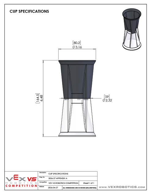
| Top opening diameter | 80.2 mm (Ø3.16″) | Manual Fig A6 |
| Waist diameter | 59.0 mm (Ø2.32″) | Manual Fig A6 |
| Total height | 164.5 mm (6.48″) | Manual Fig A6 |
| Waist Y-position | 55 mm above base | Team estimate |
| Bottom diameter | 80 mm | Team estimate |
| Wall thickness | 2.5 mm | Team estimate |
Onshape Steps
Create the document
Onshape → Create → Document. Name it Override_Cup_Placeholder_v1. Open the default Part Studio.
Sketch the half-profile on the Front plane
Click the Front plane in the feature tree → Sketch (S key). Draw the right half of the cup's outline (matching the SVG above), with a vertical centerline along the Y-axis as the axis of revolution.
Apply dimensions
Lock the sketch with these dimensions: vertical axis 164.5 mm, bottom horizontal 40 mm, top horizontal 40.1 mm, waist Y-position 55 mm, waist X-position 29.5 mm. Sketch turns black when fully defined.
Revolve 360°
Exit sketch → Revolve. Select the closed sketch region as the face, the vertical axis line as the axis. Type: Full (360°). The cup appears as a solid hourglass.
Shell to hollow
For more realistic fitment behavior, hollow the cup. Shell tool → select the top circular face as the face to remove → thickness 2.5 mm → direction inward.
Verify with Measure
Before exporting, use the Measure tool: confirm top OD = 80.2 mm, waist OD = 59 mm, total height = 164.5 mm. Fix the sketch if any value is off.
Export STEP
Right-click the part → Export → format STEP → units Millimeter → filename Override_Cup_Placeholder_v1.step.
Manual Reference
2D Profile (sketch this)
Verified vs. Estimated Dimensions
| Dimension | Value | Source |
|---|---|---|
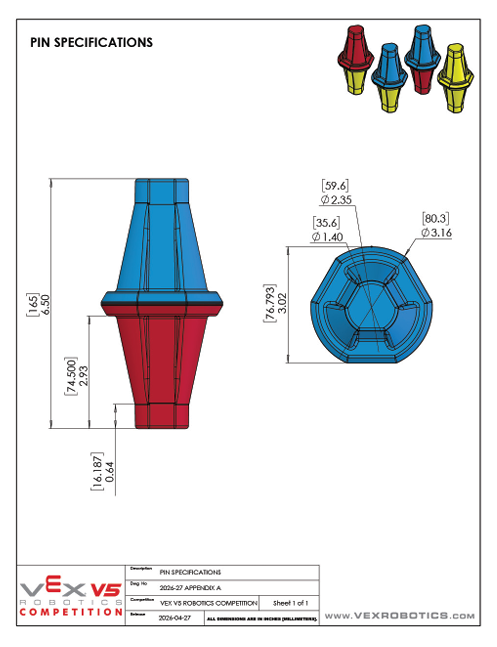
| Top hex flat-to-flat | 80.3 mm (Ø3.16″) | Manual Fig A5 |
| Mid taper diameter | 59.6 mm (Ø2.35″) | Manual Fig A5 |
| Bottom hex flat-to-flat | 35.6 mm (Ø1.40″) | Manual Fig A5 |
| Total height | 165 mm (6.50″) | Manual Fig A5 |
| Taper section height | 74.5 mm (2.93″) | Manual Fig A5 |
| Bottom flange height | 16.2 mm (0.64″) | Manual Fig A5 |
| Top hex section height | 74.3 mm | Computed: 165 - 74.5 - 16.2 |
Approach: Two Build Methods
Pins aren't radially symmetric (they're hex), so a simple revolve doesn't produce the right shape. Two practical approaches:
- Method A (preferred): stacked extrudes + loft. Sketch a hexagon, extrude the bottom flange. New sketch on top face for a smaller hex, extrude/loft up through the taper. New sketch for the top hex, extrude up. Three operations total. Result: accurate hex prism.
- Method B (faster, less accurate): revolve approximation. Sketch the cup-style half-profile and revolve. Result is a tapered cylinder, not a hex prism. Good enough for most fitment checks; not accurate for orientation-sensitive interactions.
Onshape Steps (Method A — Stacked Extrude + Loft)
Create the document and sketch the bottom hex
New document Override_Pin_Placeholder_v1. Open Part Studio. Sketch on Top plane → Polygon (regular) tool → 6 sides → flat-to-flat 35.6 mm.
Extrude the bottom flange
Exit sketch → Extrude → Blind, depth 16.2 mm → New solid. This is the bottom flange.
Sketch the top hex (on the top face of the flange)
Click on the top face of the flange → Sketch. Draw a hexagon, flat-to-flat 80.3 mm, centered on the same axis. Don't extrude yet — this is the lower profile of the loft.
Sketch the upper hex (on a parallel plane offset by 74.5 mm)
Create a new plane parallel to the Top plane, offset 74.5 mm above the flange's top face. Sketch a hex flat-to-flat 80.3 mm on this plane (same as the lower profile — the taper isn't literally tapered to a smaller dimension, the manual shows it transitioning to the same outer profile but with a different visual style).
Note: If you want the taper visible, offset the upper hex by ~5 mm and adjust. For placeholder purposes, parallel-up is fine.
Loft between the two hex sketches
Loft tool → select the lower hex sketch as profile 1, the upper hex sketch as profile 2. Operation: New solid (or Add to existing). This produces the tapered middle section.
Extrude the top section
Sketch on the top face of the loft → hex flat-to-flat 80.3 mm → Extrude Blind 74.3 mm. This is the top wider section.
Combine and verify
Use Boolean → Union to combine the three solids if they aren't already merged. Then use Measure to verify total height = 165 mm and the three hex flats match.
Export STEP
Right-click → Export → STEP → Millimeter → Override_Pin_Placeholder_v1.step.
Manual Reference
2D Profiles (sketch top, extrude up)
Verified Dimensions
| Dimension | Value | Source |
|---|---|---|
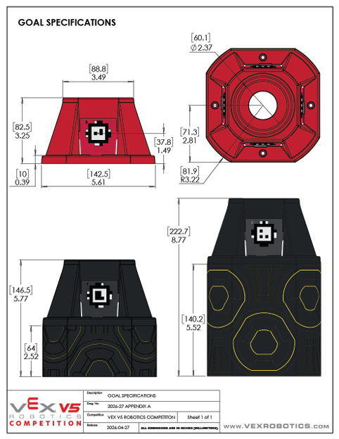
| Base square side | 142.5 mm (5.61″) | Manual Fig A7 |
| Top square side | 88.8 mm (3.49″) | Manual Fig A7 |
| Corner radius | 81.9 mm (R3.22″) | Manual Fig A7 |
| Receptacle hole diameter | 60.1 mm (Ø2.37″) | Manual Fig A7 |
| Alliance goal height | 82.5 mm (3.25″) | Manual Fig A7 |
| Short neutral height | 146.5 mm (5.77″) | Manual Fig A7 |
| Tall center height | 222.7 mm (8.77″) | Manual Fig A7 |
| Top cap thickness | 37.8 mm (1.49″) | Manual Fig A7 |
Field Quantities
The field has 9 goals total: 4 alliance-colored (2 red, 2 blue), 4 short neutrals (one per quadrant), 1 tall center neutral. Build all three sizes once; duplicate the part for the alliance and short neutral instances. All 9 goals have AprilTags on their bases.
Onshape Steps (Build the Alliance Goal First, Then Duplicate)
Create the document and sketch the base profile
New document Override_Goal_Alliance_v1. Open Part Studio. Sketch on Top plane → draw a 142.5 mm square centered on origin. Use Fillet tool with R = 81.9 mm at each corner (note: this radius is larger than the square's half-side, so corners blend into a near-circular shape — that's correct).
Extrude the base footprint
Exit sketch → Extrude → Blind, depth 10 mm (the manual shows a thin bottom layer). New solid.
Sketch the top profile (on a plane offset to alliance height)
Create a new plane offset 72.5 mm above the Top plane (Alliance goal: 82.5 mm total height − 10 mm base layer). Sketch a square 88.8 mm with R81.9 corners on this plane. This is the top profile.
Loft from base profile to top profile
Use Loft between the bottom face of the base footprint (or the original sketch) and the upper square sketch. This creates the trapezoidal frustum.
Cut the receptacle hole on top
Sketch on the top face → circle Ø60.1 mm centered on the origin. Exit → Extrude → Operation: Remove → Through all (or 37.8 mm depth). This creates the cup/pin receptacle.
Duplicate for short neutral and tall center
Save the alliance goal as STEP. Then either: (a) duplicate the document and edit the offset plane to 136.5 mm (short neutral height − 10 mm) for the second goal, then 212.7 mm for the tall center; or (b) parameterize the height in a configurations table and let Onshape generate all 3.
Export each as STEP: Override_Goal_Alliance_v1.step, Override_Goal_ShortNeutral_v1.step, Override_Goal_TallCenter_v1.step.
Manual Reference
2D Profile (cross-section + length)
Verified Dimensions
| Dimension | Value | Source |
|---|---|---|
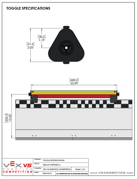
| Triangle height | 51.6 mm (2.03″) | Manual Fig A8 |
| Triangle base width | 30.2 mm (1.19″) | Manual Fig A8 |
| Extrude length | 660.2 mm (25.99″) | Manual Fig A8 |
| Field count | 4 toggles per field | Manual SC5 |
| Mount | One per perimeter side | Manual Fig A8 |
Onshape Steps
Create the document and sketch the triangle
New document Override_Toggle_Placeholder_v1. Open Part Studio. Sketch on Front plane (so the prism extrudes horizontally) → draw an isosceles triangle: base 30.2 mm wide along the X-axis, apex 51.6 mm above the base midpoint.
Extrude 660.2 mm
Exit sketch → Extrude → Blind, depth 660.2 mm. The result is a long triangular prism — that's the toggle.
Verify and consider rounded corners
Use Measure to confirm 51.6 / 30.2 / 660.2. The real toggle has slight rounding on the edges (~5 mm fillet); for a placeholder, sharp edges are fine. If you want more accuracy, apply a small Fillet on the three long edges of the prism.
Export STEP
Right-click → Export → STEP → Millimeter → Override_Toggle_Placeholder_v1.step.
The Goal of Assembly Work
Your Hero Bot assembly is where the manipulator, drivetrain, and game elements come together. It answers questions you can't answer from individual part files:
- Does the manipulator clear the cup at the top of the tall center goal (222.7 mm + cup height)?
- Does the gripper open wide enough to capture an 80 mm cup OD?
- Is the chassis low enough to fit under the midfield boundary at ≤18″ (457 mm) for the endgame?
- Does the manipulator interfere with itself when it tries to flip cup orientation?
Onshape Assembly Steps
Create the assembly
In your team's Hero Bot Onshape document → Insert tab → New Assembly. Name it HeroBot_V1_Assembly.
Insert the Hero Bot parts
Insert the drivetrain and manipulator parts you've already CAD'd. Mate them together using Fastened mates (the manipulator base is fixed to the chassis at a specific position).
Insert game elements
Insert the cup, pin, and at least one alliance goal from the STEP files you exported. Position them at expected match locations: a goal centered in front of the robot for scoring, a cup near the manipulator pickup zone, a pin in the loading area.
Run the manipulator through its range of motion
Use Mate values to drive the manipulator's revolute joints through their full angle range. Watch for collisions with the goal, the cup, or the chassis. Any collision is a design problem to fix.
Check critical clearances
For each goal size (alliance 82.5 mm, short neutral 146.5 mm, tall center 222.7 mm), confirm: (a) the manipulator can reach the receptacle from a reasonable robot stance, (b) the gripper has 5–10 mm clearance around the cup at placement, (c) the arm doesn't hit the goal's rounded corners during approach.
What to Document in Your Notebook
For each assembly check, capture a screenshot in your notebook with:
- The robot configuration (e.g., "arm at top extension, cup gripped")
- The element being interacted with (which goal size, cup, or pin)
- Any clearance issues found (and how you plan to fix them)
- The Onshape assembly URL so anyone can open it
This is orange-EDP build-log content. See build-log-entry for the entry format.
Notebook Entry Template
For each game element you CAD, your notebook entry should include the following. This is orange-EDP (Build & Program) content.
- Why this CAD exists. "Placeholder for chassis-fitment testing in
HeroBot_V1_Assembly." - Verified vs. estimated dimensions table. Reproduce the dim tables from this page's element sections, with checkmarks for what your team measured and what you estimated.
- The Onshape document URL. Anyone on the team should be able to open and edit it.
- Verification checks. Bounding-box measurements you confirmed in the Measure tool, with screenshots.
- What you'd swap for. "Replace with VEX official element CAD when published on vexrobotics.com."
When to Replace These Placeholders
Three triggers:
- VEX publishes official Override CAD on
vexrobotics.com/v5/competition/vrc-current-game. The official files are authoritative; team-built ones will always be approximations. - Your team's actual measurements show a placeholder is meaningfully wrong (e.g., the real waist is at 70 mm, not 55 mm — your manipulator clearance check was based on a wrong assumption).
- A new manual version revises any of the verified dimensions. v1.1 of the Override manual is expected August 13, 2026.
📄 Print Version
For vets working with Onshape on a single screen, this walkthrough is also available as a single-document markdown file. Drop into the team's Drive in 2026-27 Override / Resources for offline reference.
Related Pages
- spartan-hero-bot — the V1 Hero Bot spec these elements get assembled with
- mechanism-claw — manipulator architecture decision matrix; references cup and pin geometry
- onshape-mechanism — general mechanism CAD workflow; the Phase A Onshape Day 3 reference
- override-manual-summary — full manual summary with field dimensions