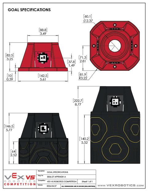
Spartan V1 Hero Bot — Spec 🦾
Spartan Design's internal V1 Hero Bot for Override 2026-27. All 6 teams start from this baseline; differentiation happens after handoff. This page is the canonical reference for what V1 is — the spec the curriculum teaches toward.
This is Spartan's team-internal V1 Hero Bot. Decided by Coach Tansopalucks before the season, refined against the v0.1 manual. All 6 teams build to this baseline, then iterate post-handoff.
This is NOT VEX's official Override Hero Bot. VEX's Hero Bot (the canonical "what does the official starter robot look like?" reference) had not yet been published as of April 28, 2026. Historically VEX releases the Hero Bot 4–6 weeks after the game manual drops — expect late May or early June 2026. When VEX publishes, this page will compare the Spartan V1 spec to the VEX official Hero Bot and highlight any architecture deltas.
What V1 Hero Bot Is
- 4-motor clawbot drivetrain — fixed across all 6 teams, sized for the 55W cap (R11a) and the no-PTO rule (R11b)
- Manipulator arm — architecture is a team choice: sequential single-grip, dual-grip, hybrid intake, or continuous roller-pinch. See Section 3 (Manipulator) for the decision framework
- Limit switch at arm reference (typically arm-fully-down position) — mechanical safety + a known reference for sensor zeroing
- Position sensors — IMU for chassis heading, Potentiometer V2 for arm angle (Pot V2 is the V1 baseline; Rotation Sensor is the upgrade path)
- EZ-Template chassis with PROS as the toolchain; LemLib mentioned for completeness but not the V1 baseline
What V1 Hero Bot Is NOT
- Not the final competition robot. V1 is a starting point. After handoff (Mtg 12, June 4), each team iterates V2/V3 based on what they learned and their team's competition strategy.
- Not Override-optimized for max scoring. V1 is designed for working, not competitive. It can pick up cups + pins, place them on goals, drive cleanly, run a basic auton, and survive an endgame collapse. It does not have toggle-flipping, advanced descoring, or skills-route-grade odometry.
- Not unique to one team. Same V1 baseline for all 6 Spartan teams — this is by design, so vets can teach across teams during Phase A and so handoff is uniform.
Why It's This Way
Three principles drove the V1 spec:
- The 55W cap is the constraint (R11a). Override locks drivetrains to 55W of motor power, with no PTO from drivetrain to other subsystems (R11b) and an 88W total cap on the whole robot (R10a). 4×11W blue motors = 44W, leaving 44W for the manipulator and any future expansions.
- The 1+1 possession limit is the manipulator constraint (SG6). One cup + one pin maximum at any time. This rules out magazine-feed accumulators and makes the manipulator architecture a real engineering decision — teams pick how to handle pin-then-cup sequencing.
- The midfield endgame is positional, not climbing (SG12, SG12.1). Last 10 seconds, must be inside midfield, ≤18″ tall. V1 doesn't need a climbing endgame — just an arm that can collapse to legal height.
Configuration
| Motor Count | 4 motors (down from 6 on the post-regional Push Back V1) |
| Motor Type | 4×11W blue cartridge, ports 1–4 |
| Total Drivetrain Power | 44W of the 55W cap (R11a) — 11W headroom |
| PTO | None — PTO from drivetrain motors is explicitly prohibited (R11b) |
| Wheels | 4″ omni wheels, 4-wheel direct drive (no chain) |
| Heading Reference | V5 IMU on chassis |
Programming Spec
- EZ-Template chassis —
ez::Driveconstructed with the 4 motor ports + IMU port - PROS as the toolchain — not VEXcode, not Blocks. EZ-Template runs on top of PROS
- Tank-style driver control for V1 — left stick / right stick = left side / right side. (Cheesy drive is an upgrade option for advanced teams)
Why This Drivetrain
- 4-motor blue is rule-legal with margin. 44W against the 55W cap leaves 11W of headroom — if VEX issues a future Q&A clarification that tightens the math, we're not at the edge.
- Direct drive, no chain. Chain adds maintenance overhead. For V1, simpler is better. Teams that want chained drivetrains can add it post-handoff.
- 4″ omni wheels balance speed and torque. Smaller wheels (3.25″) give more torque for pushing but less top speed; larger (4.125″) reverse the tradeoff. 4″ is the V5RC default and works fine for V1.
- IMU is mandatory. Encoder-only odometry drifts. The IMU gives chassis heading independent of wheel slip, which matters in autonomous and on tile seams.
The Constraint That Drives Architecture
Per SG6, your robot can hold 1 cup AND 1 pin at any given time, no more. This means:
- You can't build a magazine-feed accumulator (no "hold 5 pins, deploy in sequence")
- Every scoring sequence is at most pickup-pin → place-pin → pickup-cup → stack-cup, then drive to next goal
- The architecture choice is about how to make that 4-step sequence as fast and reliable as possible
Four Architectures Teams Can Pick
Architecture A — Sequential Single-Grip
One gripper that handles both pins (40mm dia) and cups (80mm dia). Picks up one element at a time. Simpler mechanism, slower cycle.
- Win: simpler build, fewer motors, lower port budget, easier to debug
- Lose: 4-step sequence is slow because gripper must re-grab between steps
- Best for: rookie-heavy teams, first-build experience, conservative strategies
Architecture B — Dual-Grip
Two grippers on the same arm: one sized for the pin, one for the cup. Picks up both elements before traveling, deploys in sequence at the goal.
- Win: faster cycle, fewer drives across the field, more cycles per match
- Lose: mechanical complexity, higher motor count, more failure modes
- Best for: experienced teams targeting high cycle counts, or teams with strong fabrication
Architecture C — Hybrid Intake-and-Grip
A small ground intake that lifts pins/cups into a holding zone, with a separate placement gripper. Only viable if cup + pin both fit in one feeder.
- Win: hands-off pickup (driver doesn't have to align gripper precisely)
- Lose: Cup hourglass shape and pin cylinder shape don't naturally co-feed; requires careful geometry design
- Best for: advanced teams, V2/V3 iterations
Architecture D — Continuous Roller-Pinch (Compression Intake)
Two opposed flex wheels mounted on a lift arm, rotating inward to compress and grip a single element. Same wheel pair handles both pins and cups via a configurable gap (~1.65″ for the pin mid-section, ~1.50″ for the cup base) tuned for one element type per match. Reverse the motor to outtake. See override-intake-geometry for the full geometry analysis (Gap = S − D math, 3″ vs 2″ flex wheel trade-offs, star-cut wheel mod).
- Win: single motor for the entire intake (~11W from R10a); fastest pickup-to-secured time of any pattern; no precise alignment required — the rollers grab as the robot drives over the element
- Lose: only handles one element at a time, so it's a Sequential pattern at heart (cycle time gain over Architecture A is at pickup, not transport); flex wheels degrade with use and need replacement mid-season; cup gripping is workable but less reliable than top-down claw on the cup's rim
- Best for: teams prioritizing pickup speed and driver simplicity over peak cycle count; teams whose strategy is dense pin-cycling within a single quadrant rather than full-field pin-then-cup runs; rookie-friendly because grip alignment is forgiving
What the Manipulator Must Reach
Each team decides during Mtgs 4–8 (Onshape phase) which architecture fits their strategy. See the full decision matrix in mechanism-claw § Three Architectures.
Cup Orientation Is a Mechanism Concern
Per SC3, pins score per half: a pin half in the transparent side of a cup scores; a pin half in the opaque side does not. Two ways to handle this:
- Sense-then-place — an Optical Sensor on the manipulator detects cup orientation, and the gripper rotates the cup before placement. See sensors-optical § Override Use Cases.
- Always-flip — mechanically flip the cup at pickup so it's always transparent-side-up before placement. Simpler, but inflexible (can't flip back if you change your mind).
- Don't bother (V1) — for V1, place cups in whatever orientation the gripper happens to capture them. Half your placements will be sub-optimal, but you build faster. Iterate on orientation control in V2.
V1 Baseline Sensors (mandatory)
| IMU (V5 Inertial Sensor) | Smart port. Provides chassis heading for autonomous and odometry. Required. See imu-setup + imu-calibration. |
| Limit Switch | 3-wire ADI. Mounted at arm-fully-down reference position. Provides mechanical safety + zeroing reference for arm angle sensor. See sensors-discrete § Switches. |
| Potentiometer V2 | 3-wire ADI. Mounted on arm pivot. Reads arm angle absolutely (no zeroing needed on power-up). See sensors-discrete § Potentiometer V2. |
Why Pot V2 (Not Rotation Sensor) for V1 Arm
This is a real decision worth understanding:
- Pot V2 is half the cost ($30 for 2-pack vs. $50 each for the Rotation Sensor) — matters across 6 teams
- Pot V2 uses an ADI port — saves Smart ports for Vision/Distance/Optical/Rotation sensors that have no ADI alternative
- Pot V2 is absolute — on power-up, you know the arm angle. Rotation Sensor is relative (needs zeroing each session)
- 1° precision is plenty for arm presets at 6° / 14° / 24°. The Rotation Sensor's 0.01° resolution doesn't buy you anything for goal-height presets
For the full pot-vs-rotation comparison, see sensors-rotation § Decision Matrix.
V2 Upgrade Path (Optional, Post-Handoff)
| 2× V5 Rotation Sensors | For odometry tracking wheels. Required if targeting high skills scores. Smart ports. See sensors-rotation + odom-pod-build. |
| V5 Distance Sensor | Front-mounted, walls/objects. For wall-following autons or pre-scoring alignment. See distance-sensor. |
| V5 Optical Sensor | Manipulator-mounted, cup orientation detection. See sensors-optical § Override Use Cases. |
| V5 GPS Sensor | Skills-run drift correction. Best for 60-second skills routes that traverse the full field. See sensors-gps. |
| V5 AI Vision Sensor | If AprilTags get deployed (v0.1 manual is silent — tentative). See sensors-apriltags. |
The 8 steps below are the same for every V5 sensor — IMU, optical, distance, rotation, GPS, vision. Skipping a step (especially Step 6, isolated testing) is the most common reason a new sensor "doesn't work."
1. Pick the Right Sensor for the Problem
Don't add a sensor because it's cool. Add it because it solves a known issue you've already hit. Common Override-relevant additions, in priority order from sensors-roadmap:
- V5 Optical Sensor — cup orientation detection on the manipulator. Override-specific value because of the opaque/transparent cup rule (SC3).
- 2× V5 Rotation Sensors — for tracking-wheel odometry. Required if targeting high skills scores or precise auton paths.
- V5 Distance Sensor — front-mounted, for wall alignment and approach distance during scoring runs.
- V5 GPS Sensor — absolute (X, Y) position from field-edge GPS strips. Best ROI on 60-second skills routes that traverse the full field.
- V5 AI Vision Sensor — AprilTag detection if AprilTags are deployed (v0.1 manual is silent — treat as tentative).
The V2 upgrade table in Section 4 above lists each with its specific role on the Hero Bot.
2. Reserve the Port
Plan port allocation before you wire anything. The V5 Brain has two port families:
- Smart ports (21 total). Used by motors and Smart sensors. The V1 Hero Bot drivetrain takes 4 (ports 1–4) plus 1 for the IMU plus 1–2 for the manipulator motor(s). That leaves ~14 free for Smart sensors.
- ADI / 3-wire ports (8 total). Not used by drivetrain motors. The V1 Hero Bot uses ADI A for the limit switch and ADI B for Pot V2. That leaves 6 free.
Smart-port sensors: IMU, Optical, Distance, Rotation, GPS, AI Vision. ADI sensors: Limit Switch, Pot V2, bumper switches, LEDs. Always document the port allocation in your Owner's Manual.
3. Mount It Mechanically
Each sensor has its own mounting rules. The wrong mount produces wrong readings — or worse, intermittent readings that fail at competition.
- IMU — flat on the chassis, ideally near the center of mass. Keep it away from motors and the battery (magnetic interference). Orientation matters — the IMU's yaw axis must align with vertical for chassis heading to be meaningful.
- Distance Sensor — front of chassis, aimed at what you want to measure, with no obstructions in the cone. ~13.5″ deadzone in front. See distance-sensor-mounting.
- Optical Sensor — close to the target (10–25mm), consistent lighting. On the manipulator for cup orientation, this means mounting where the cup will pass within range during pickup.
- Rotation Sensor — coupled to a tracking wheel via a hex shaft, rigid mount with no slop. Two of them (perpendicular axes) for full odometry. See sensors-rotation + odom-pod-build.
- GPS Sensor — ~10.5″ mounting height with clear line of sight to all 4 perimeter strips. The GPS Field Code (276-7823) is required.
4. Wire It
Smart sensors use the 4-pin Smart cable. ADI sensors use the 3-wire cable (signal / +5V / ground). Cable management matters: secure the cable so it doesn't get pinched in moving mechanisms or yanked when the robot reverses. Leave a service loop near the brain so you can re-route later. Write down which port each sensor occupies the moment you plug it in — not later.
5. Declare It in PROS Code
Add the sensor object in your code with the port number you reserved. Examples:
pros::Imu imu(11);— Smart port 11pros::Distance dist(12);— Smart port 12pros::Optical optical(13);— Smart port 13pros::Rotation rot_x(14);— Smart port 14pros::Gps gps(15);— Smart port 15 (276-7405)pros::adi::DigitalIn limit_switch('A');— ADI port Apros::adi::Potentiometer pot('B', pros::E_ADI_POT_V2);— ADI port B
Declare the sensor object once at the file scope (typically in main.cpp or a dedicated sensors header), not inside individual functions.
6. Test It in Isolation
Before wiring it into auton or driver code, just print the raw value to the brain screen or terminal. Confirm sane readings. This is the single most important step — the rest of debugging gets dramatically harder if you don't know whether the sensor is healthy.
- Print to the brain screen with
pros::lcd::print(line, "dist: %.2f", dist.get()) - Or print to terminal with
printf("dist: %.2f\n", dist.get());and read it viapros terminal - Move the sensor around / change its environment / cover it with your hand — readings should change in the way you expect
- If readings are zero, NaN, or stuck, fix wiring or port assignment before going further
7. Calibrate If Needed
Some sensors need calibration; some don't.
- IMU — needs
imu.reset()at startup with the robot stationary, plus a ~3-second wait for convergence. See imu-calibration. - GPS — requires the V5 GPS Field Code (276-7823) on the field. Heading converges in 3–5 seconds after the robot is in a position with line-of-sight to a strip.
- Optical Sensor — LED on (
optical.set_led_pwm(75)) plus threshold tuning for your lighting conditions. Take readings of opaque cup side vs. transparent cup side under match lighting and pick the threshold halfway between. - Rotation Sensor — needs zeroing at session start (it's relative, not absolute). Call
rot_x.reset_position()on startup. - Pot V2 — absolute. No calibration needed.
- Distance Sensor — no calibration. Be aware of the ~13.5″ deadzone.
- Limit Switch — no calibration. Confirm direction (active high vs active low) by reading the value while pressed and unpressed.
8. Integrate Into Auton / Driver Code
Now use the sensor data for actual decisions. Two rules:
- Always set safety bounds. Timeouts so a stuck sensor doesn't freeze the robot. Range checks so a wild reading doesn't drive an unsafe action. EZ-Template's
chassis.pid_wait()family accepts exit conditions for exactly this. - Test driver mode first, then auton. Driver mode lets you watch the robot react in real time and abort if needed. Auton runs blind — only commit auton logic after the driver-mode integration is solid.
Apr 27–May 1
May 4–8
May 11–15
May 18–22
May 25–29
Jun 1–5